Rock Bolt Manufacturer & Rock Reinforcement Solutions

Sinorock is a leading manufacturer of anchoring solutions, specializing in the development, production, and global supply of high-quality anchoring products.

With over 20 years of manufacturing experience, our products are used in more than 80 countries worldwide.

Operating two production facilities with over 100 advanced machines and 20 automated hollow anchor bar production lines, Sinorock is Asia’s leading supplier of large-diameter self-drilling anchor bars, with manufacturing capabilities up to 200 mm in diameter.

Product Categories

Sinorock provides reliable self-drilling anchor systems and rock reinforcement products engineered for challenging construction environments worldwide

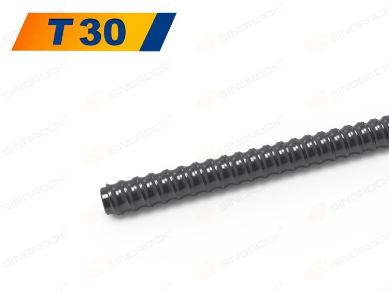
T30 Self-Drilling Hollow Anchor Bolt
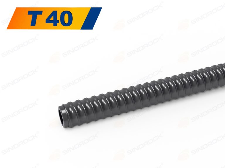
T40 Self-Drilling Rock Bolt
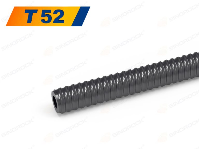
T52 Self-Drilling Anchor Rock Bolt
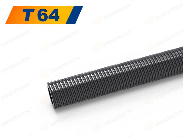
T64 SDA Bolt
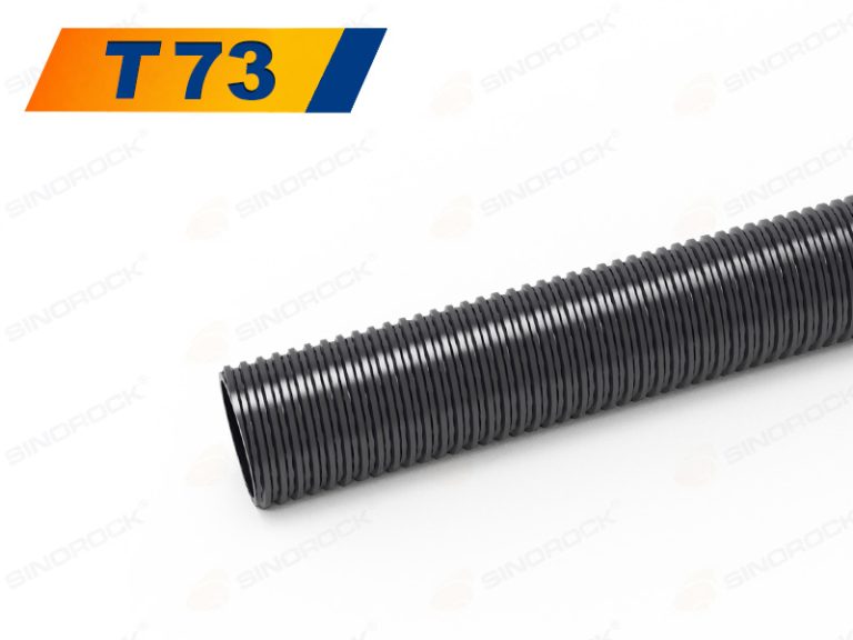
T73 High-Load Self-Drilling Rock Bolt
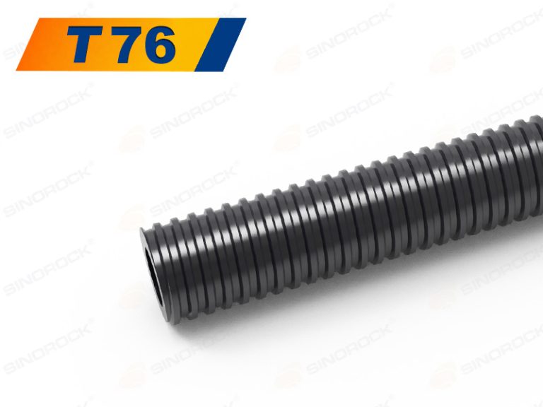
T76 Self-Drilling Rock Bolt
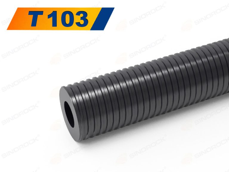
T103 Self-Drilling Anchor Bolt
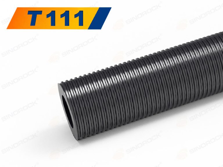
T111 Large-Diameter Self-Drilling Anchor Bar
1 2 3
T30 Self-Drilling Hollow Anchor Bolt
T40 Self-Drilling Rock Bolt
T52 Self-Drilling Anchor Rock Bolt
T64 SDA Bolt
T73 High-Load Self-Drilling Rock Bolt
T76 Self-Drilling Rock Bolt
T103 Self-Drilling Anchor Bolt
T111 Large-Diameter Self-Drilling Anchor Bar
1 2
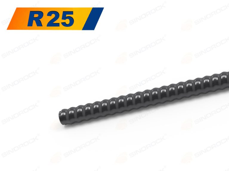
R25 Self-Drilling Anchor Bolt
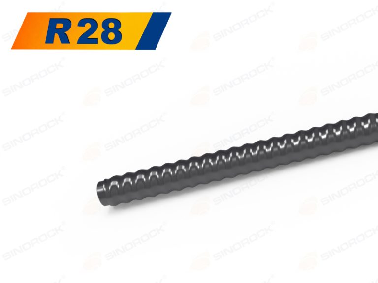
R28 SDA Bolt
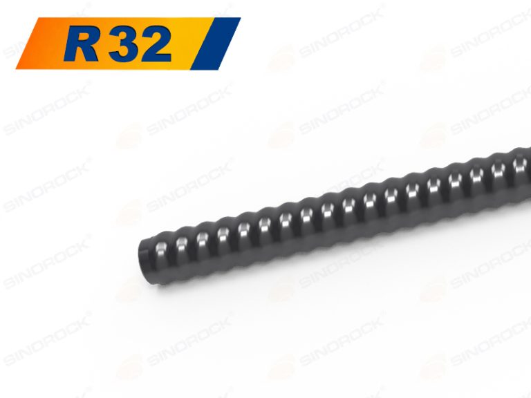
R32 Self-Drilling Rock Bolt
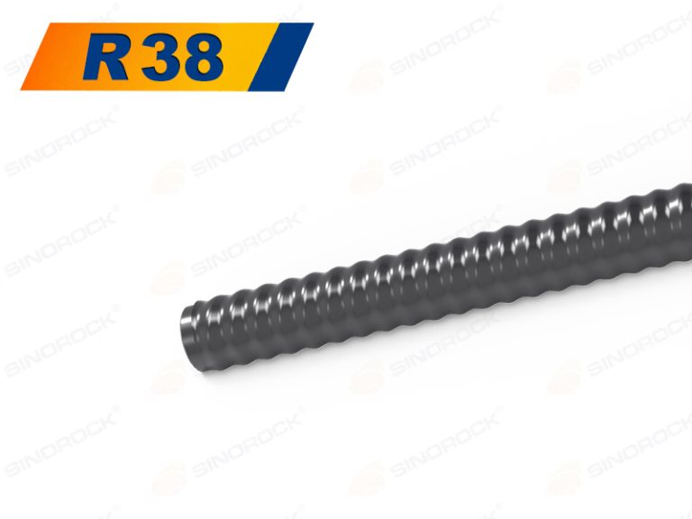
R38 Self-Drilling Anchor Bolt
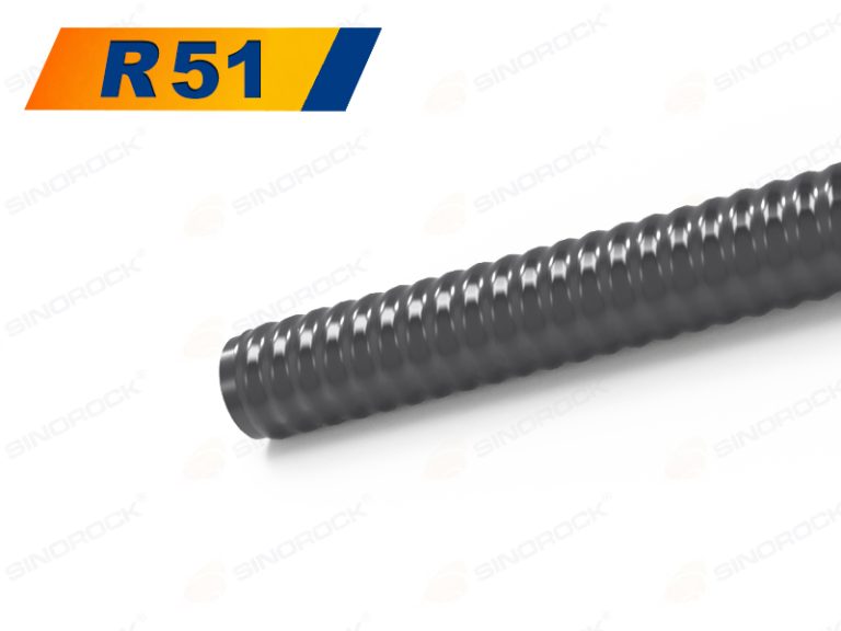
R51 Self-Drilling Anchor Bolt System
High-Elongation Self-Drilling Anchor Bolt System

The high-elongation self-drilling anchor bolt system is a solution developed for highly deformable ground conditions. With an elongation of A ≥ 15%, it can accommodate ground deformation through controlled elongation, absorb deformation energy, and help maintain surrounding rock stability.

High-Strength Self-Drilling Anchor Bolt System

The high-strength self- drilling anchor bolt system is a high-performance geotechnical support solution designed for high-load and demanding ground conditions. With tensile strength of 900–1,200 MPa or higher, it provides enhanced load-bearing capacity and pull-out resistance while maintaining a compact cross-sectional size.

low-carbon self-drilling anchor bolt system

The low-carbon self-drilling anchor bolt system is a solution designed for efficient ground reinforcement with reduced carbon emissions. Manufactured from low-carbon alloy steel with optimized material and production methods, helps reduce material-related energy consumption and carbon emissions while maintaining effective construction performance.

Applications

Reliable Solutions for
Mining Operations

Self-drilling rock bolts provide efficient support for open-pit slopes and underground excavations. They improve rock stability, accelerate excavation progress, and reduce overall support costs in challenging mining conditions.

Advanced Solutions for
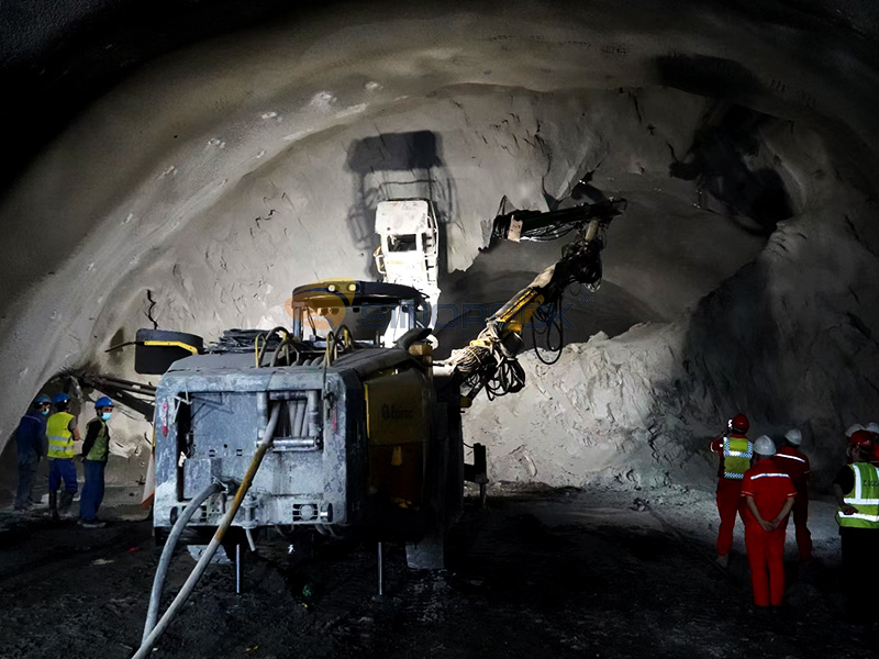
Safe Tunnel Construction

Designed for demanding tunnel environments, self-drilling anchor systems enhance ground stability and improve construction efficiency.

Strong Solutions for
Foundation Projects

Self-drilling anchor bolts effectively transfer structural loads, improve bearing capacity, and provide reliable reinforcement for foundations, bridges, towers, and other critical infrastructure projects.

Effective Solutions for
Slope Stabilization

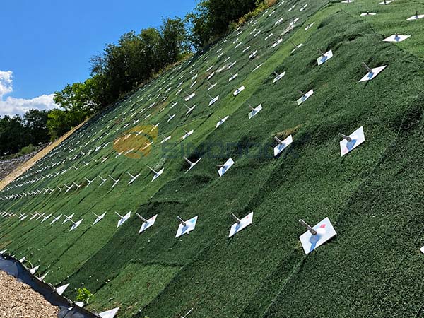
Self-drilling rock bolts strengthen unstable slopes by resisting tensile and shear forces. They are widely used for slope protection, retaining structures, rockfall prevention, and embankment stabilization.

OUR SERVICE ADVANTAGES
Shield Icon Enlarged

20+ YEARS OF EXPERTISE

Extensive experience in geotechnical anchoring, delivering optimized solutions for diverse geological and construction conditions.

Gear Icon Enlarged

FULL-PROCESS SERVICE

Supporting every project stage from investigation and testing to training and site assistance, ensuring efficient and successful implementation.

Latest News

Company News

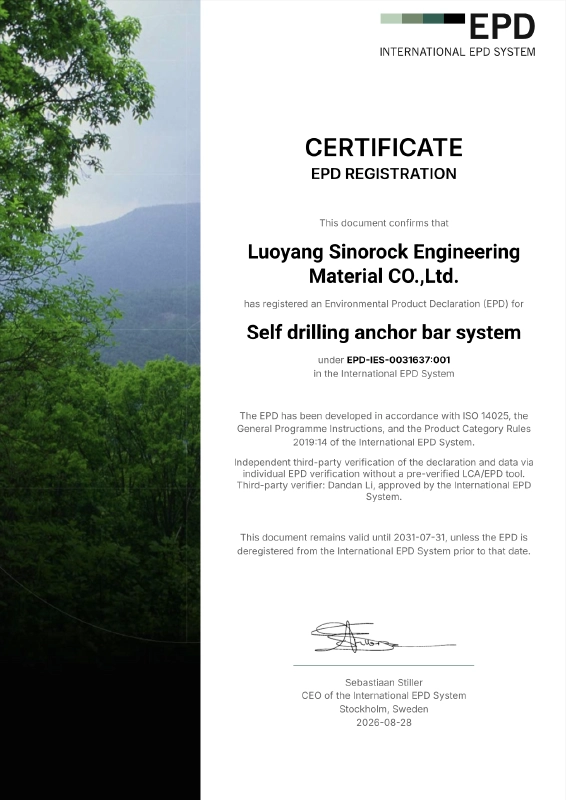
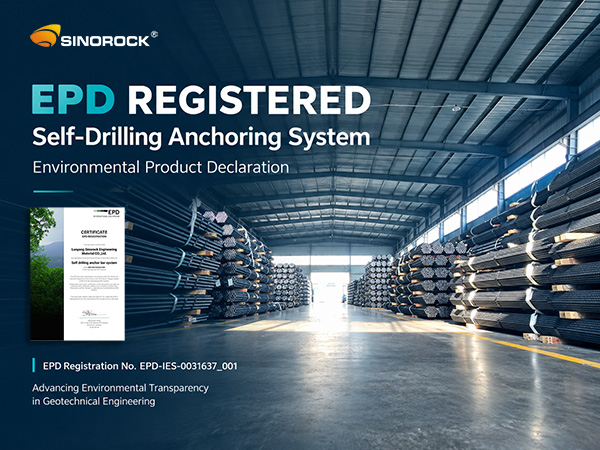
Luoyang Sinorock Engineering Material Co., Ltd. has successfully registered an Environmental Product Declaration (EPD) for its Self-Drilling Anchor Bar System under the International EPD System, marking another important milestone in Sinorock’s commitment to environmental transparency and sustainable manufacturing.

As sustainability becomes an increasingly important consideration in global construction and infrastructure projects, customers and project owners are paying greater attention not only to product performance and quality, but also to the environmental impact of construction materials throughout their life cycles.

The EPD registration provides transparent and standardized environmental information about Sinorock’s Self-Drilling Anchor Bar System, helping customers and project stakeholders make more informed decisions when evaluating materials for sustainable construction projects.

EPD Registration Based on International Standards

Sinorock Self-Drilling Anchoring System Completes EPD Registration

According to the EPD certificate, Sinorock’s Self-Drilling Anchor Bar System has been registered under EPD-IES-0031637:001 within the International EPD System.

The EPD has been developed in accordance with ISO 14025. the General Programme Instructions of the International EPD System, and Product Category Rules (PCR) 2019:14.

The declaration and underlying data have also undergone independent third-party verification, providing an additional level of credibility and transparency to the environmental information presented in the declaration.

The EPD certificate was issued on August 28. 2026. and remains valid until July 31. 2031. unless the EPD is deregistered from the International EPD System before that date.

Learn More About Sinorock’s EPD Certification

Supporting Sustainable Ground Engineering

EPD registration

As a professional manufacturer of self-drilling anchor systems, Sinorock is committed to providing reliable products for demanding geotechnical and ground engineering applications. Its self-drilling anchor system integrates drilling, grouting, and anchoring functions, providing an efficient solution for applications such as slope stabilization, tunneling, mining, foundation reinforcement, and other ground-support projects.

The EPD registration adds an important environmental dimension to the product information available to customers. By providing independently verified environmental data, it supports greater transparency throughout the product life cycle and helps project stakeholders incorporate environmental considerations into material selection.

A Further Step Toward Sustainable Manufacturing

Self-Drilling Anchor Bolts Active Rock Reinforcement Typical Applications

For Sinorock, EPD registration is more than a certification. It reflects the company’s ongoing efforts to improve manufacturing processes, strengthen environmental management, and respond to the growing demand for more sustainable solutions in the global construction industry.

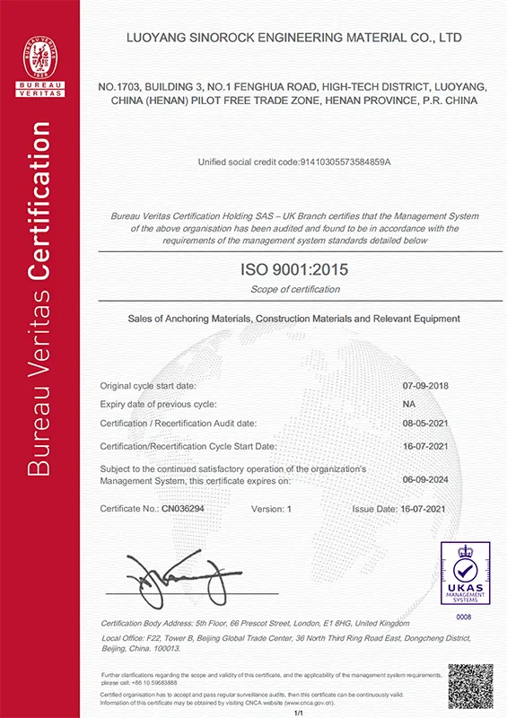
Sinorock continues to invest in process optimization, manufacturing efficiency, quality management, and technological development. The company also maintains environmental management and other internationally recognized certification systems as part of its broader approach to responsible manufacturing.

By combining product performance, manufacturing quality, and environmental transparency, Sinorock aims to provide customers with reliable anchoring solutions that meet the evolving requirements of modern geotechnical engineering.

Conclusion

The successful EPD registration of Sinorock’s Self-Drilling Anchor Bar System represents an important step in the company’s sustainability journey.

Going forward, Sinorock will continue to focus on quality, innovation, environmental responsibility, and sustainable manufacturing, while working closely with customers and partners around the world to provide more efficient and responsible solutions for ground engineering projects.

EPD registration is a new milestone for Sinorock — and another step toward a more transparent and sustainable future for geotechnical engineering.

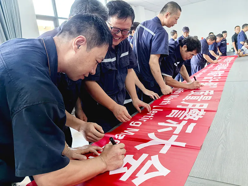
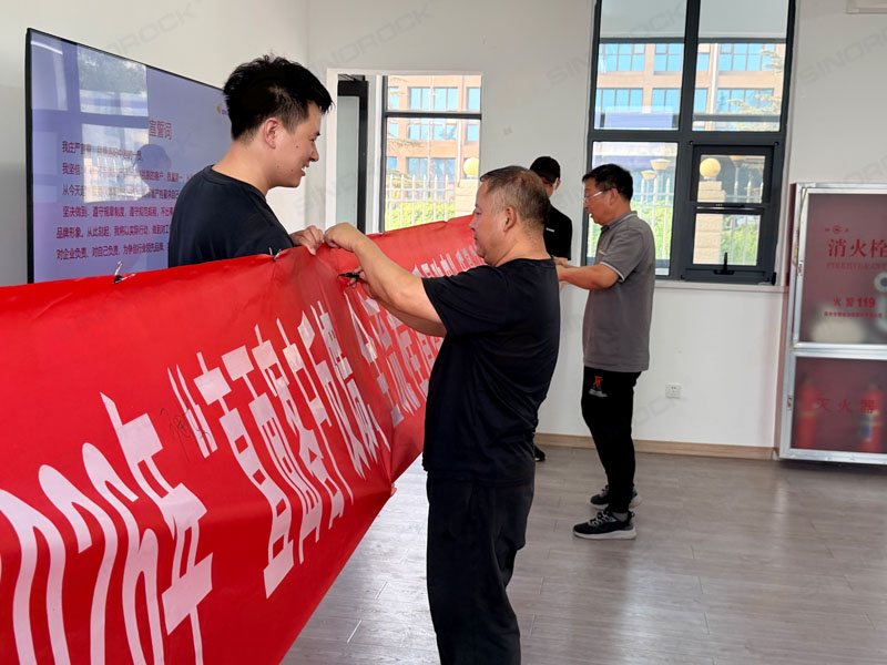
July 2026 — SINOROCK successfully completed its annual Quality Month Campaign with the theme of “Addressing Customer Feedback and Eliminating Quality Risks Across the Entire Process.”

The campaign aimed to strengthen employees’ quality awareness, encourage full participation in quality management, and build a company-wide culture where everyone values, contributes to, and continuously improves product quality.

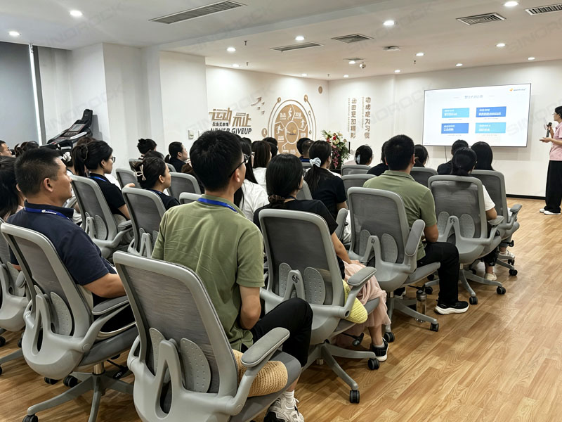
Throughout the month, SINOROCK organized a series of activities, including quality awareness meetings, customer complaint reviews, quality risk inspections, quality knowledge competitions, professional training sessions, and internal quality communication activities. These initiatives further integrated quality management into every department and every stage of production.

Customer Feedback Drives Continuous Improvement

Customer Feedback Drives Continuous Improvement

Customer feedback is an essential source for identifying potential quality issues and improving products and processes.

During Quality Month, SINOROCK conducted customer complaint review meetings, analyzing real cases from customer feedback, identifying root causes, and developing targeted improvement measures.

Through these case studies, employees gained a deeper understanding of how product quality impacts customer satisfaction and project performance. By transforming customer feedback into practical improvement actions, SINOROCK continues to optimize its quality management system and enhance product reliability.

Quality Is Everyone’s Responsibility

Quality Is Everyone’s Responsibility

Quality is not only the responsibility of the quality department — it is a commitment shared by every employee.

During the “Everyone Talks About Quality” communication sessions, employees from different positions shared their understanding of quality based on their daily work and responsibilities.

At the same time, SINOROCK organized a company-wide quality risk inspection activity. Employees actively participated in identifying potential risks within production processes, reporting issues, and proposing improvement suggestions.

These activities helped strengthen employees’ ability to identify and prevent quality problems, promoting a transition from “solving problems after they occur” to “preventing problems before they happen.”

Improving Skills Through Learning and Competition

SINOROCK 2026 Quality Month

To further enhance employees’ professional knowledge and practical quality control capabilities, SINOROCK carried out various training sessions and competitions during Quality Month.

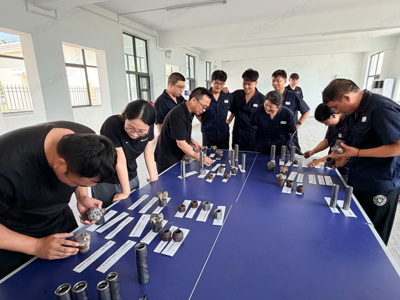
The “Product Matching Challenge” focused on 15 similar and easily confused product types. Participants were evaluated on their product identification accuracy and completion efficiency, improving their understanding of product specifications and classifications.

SINOROCK also organized a Quality Knowledge Competition featuring a 200-question quality knowledge database. The competition combined theoretical knowledge with real quality cases from company records, helping employees better understand quality standards and practical problem-solving methods.

In addition, professional training sessions were conducted, including:

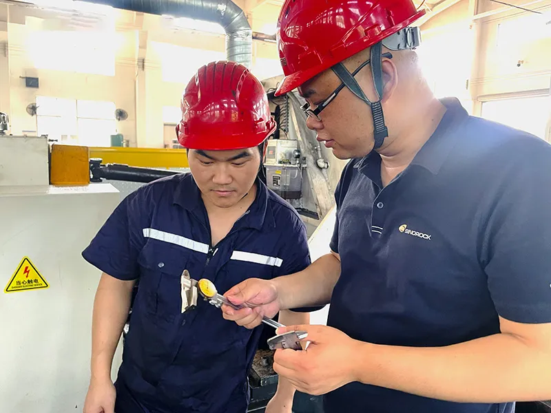
  • Hardness tester operation training;
  • Product inspection knowledge sharing;
  • Inspection procedures and standards training;
  • Product inspection specification training.

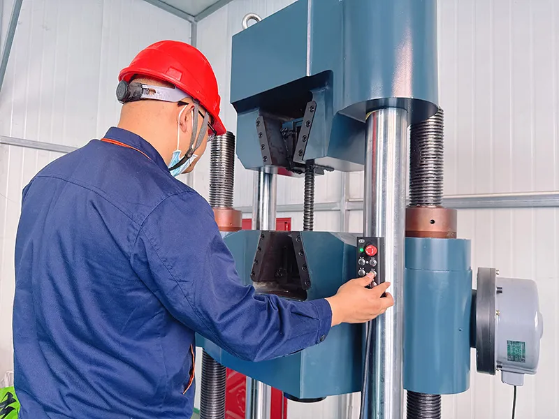
These programs further improved employees’ capabilities in product inspection, process control, and quality assurance.

Strengthening Quality Awareness Through Real Cases

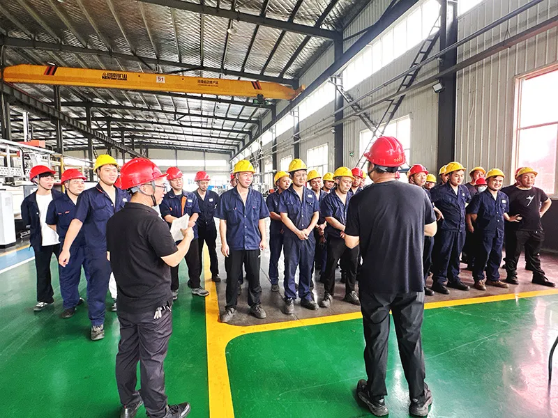
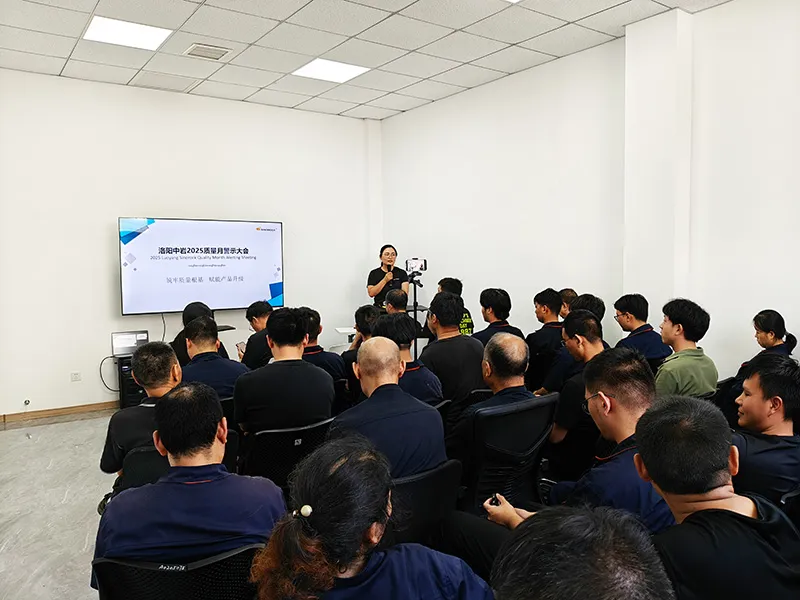
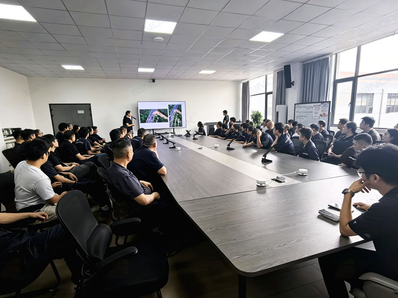
During Quality Month, SINOROCK held quality awareness meetings in different locations.

On July 13. the Quality Warning Conference was organized in Changzhou. On July 14. similar meetings were held at the Luoyang office and Luoyang branch.

Through reviewing quality-related cases and sharing lessons learned, these meetings further reinforced employees’ understanding of the importance of product quality and encouraged everyone to take greater responsibility for quality improvement.

Quality Is a Long-Term Commitment

Quality Is a Long-Term Commitment

Although Quality Month was carried out throughout July, SINOROCK’s commitment to quality improvement extends far beyond a one-month campaign.

Through meetings, practical training, competitions, inspections, and internal communication activities, quality awareness has been further integrated into daily operations.

“Addressing Customer Feedback and Eliminating Quality Risks Across the Entire Process” represents not only the theme of the 2026 Quality Month Campaign but also SINOROCK’s long-term commitment to customer-oriented quality management.

Moving forward, SINOROCK will continue to focus on customer needs, strengthen quality control throughout the entire production process, proactively identify and eliminate potential risks, and continuously improve product quality and service capabilities.

Driven by continuous improvement and a strong commitment to quality, SINOROCK will continue providing reliable, high-quality self-drilling anchor bolt products and engineering solutions to customers worldwide.

Industry News

What Is a Combination Rock Bolt?
What Is a Combination Rock Bolt

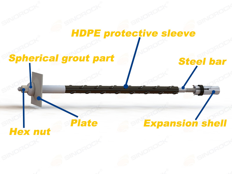
A combination rock bolt is a mechanically anchored, post-grouted rock reinforcement system designed to provide both immediate mechanical support and long-term reinforcement. It combines the advantages of mechanical end anchorage and full-length grouting, making it suitable for underground and geotechnical engineering projects where reliable load transfer, structural stability, and long-term durability are essential.

Unlike conventional mechanical rock bolts, which rely primarily on an expansion mechanism at the bolt head, a combination rock bolt incorporates an additional grouting system to improve the anchorage performance and provide enhanced protection against corrosion.

Its working principle involves two complementary anchoring mechanisms:

  • Mechanical anchorage: An expansion shell at the embedded end of the bolt expands against the borehole wall, establishing an initial anchorage point and allowing the bolt to be tensioned.
  • Grouted anchorage: Cementitious grout is subsequently injected through the grouting assembly, filling the surrounding spaces and forming a more comprehensive reinforcement system after curing.

By integrating these two mechanisms, the combination rock bolt provides an effective solution for projects requiring immediate support during construction and durable reinforcement throughout the service life of the structure.

The system is particularly suitable for underground tunnels, mining excavations, rock slopes, underground caverns, and infrastructure foundations exposed to demanding environmental conditions.

Working Principle of a Combination Rock Bolt
Working Principle of a Combination Rock Bolt

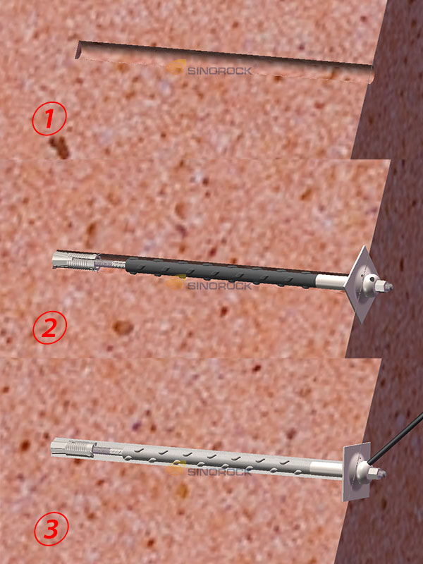
The defining feature of a combination rock bolt is the combination of mechanical anchorage and subsequent grouting. Rather than relying on a single anchoring mechanism, the system provides support through two successive stages.

Mechanical End Anchorage

The mechanical anchoring mechanism is located at the embedded end of the bolt and generally consists of an expansion shell assembly.

After the bolt is inserted into the pre-drilled borehole, the expansion shell is activated through the installation process. Its components expand outward and establish contact pressure against the borehole wall.

This creates a mechanical anchorage point that enables the bolt to be tensioned before grouting.

The main functions of mechanical end anchorage include:

  • Providing initial anchoring force immediately after installation.
  • Allowing the bolt to be tensioned and preloaded.
  • Establishing a reliable load-transfer point between the bolt and surrounding rock.
  • Reducing dependence on grout curing time during the initial support stage.

The expansion shell is therefore particularly important in construction conditions where early stabilization is required.

Post-Grouting Reinforcement

Following mechanical anchorage and tensioning, cementitious grout is injected through the dedicated grouting assembly.

The grout fills the designated spaces around the bolt and its protective components. After curing, it forms a hardened grout body that improves the interaction between the bolt and surrounding ground.

The main functions of post-grouting include:

  • Improving load transfer between the bolt and surrounding rock.
  • Providing additional anchorage along the bolt length.
  • Filling surrounding voids and designated annular spaces.
  • Reducing the exposure of steel components to corrosive groundwater and environmental agents.
  • Enhancing the long-term stability and durability of the reinforcement system.

The actual grout distribution and bonding performance depend on borehole geometry, grout properties, injection pressure, geological conditions, and installation quality.

Combined Anchorage Mechanism

The combination of mechanical anchorage and grouting provides a more comprehensive reinforcement approach than relying exclusively on either mechanism.

Mechanical anchorage establishes an initial load-bearing connection, while post-grouting develops additional bonding and protective functions.

This makes a combination rock bolt particularly useful in applications where both early-stage support and long-term structural performance are important.

Structure and Main Components
Combination Rock Bolt

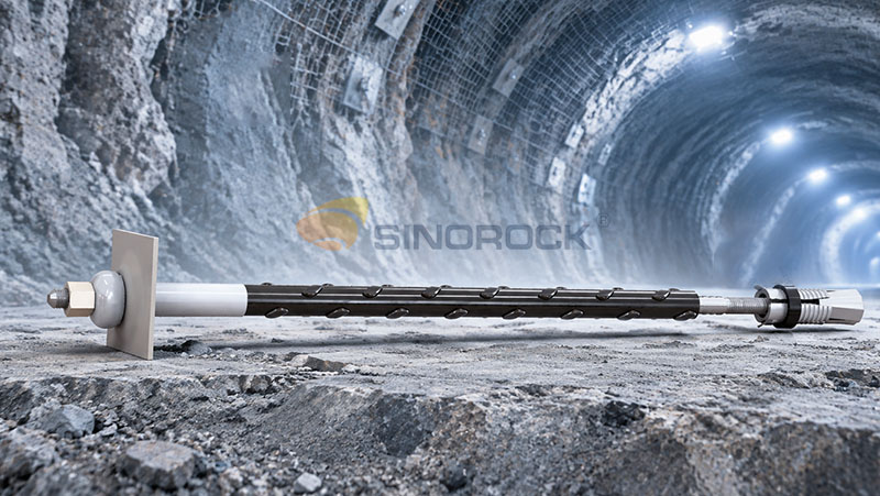
A combination rock bolt consists of a steel reinforcing bar and several functional accessories. Each component contributes to mechanical anchorage, load transfer, grouting, installation, or corrosion protection.

The main components include:

  1. Steel bar
  2. Expansion shell
  3. Hex nut
  4. Spherical grout part
  5. Bearing plate
  6. HDPE protective sleeve

Steel Bar

The steel reinforcing bar is the primary load-bearing component of the system. It transfers tensile forces from the bearing plate and mechanical anchorage assembly into the surrounding rock mass.

The bar is manufactured from high-strength reinforcing steel, with both ends machined with threads to accommodate the associated components.

Key functions:

  • Carries tensile loads generated by rock movement and structural loading.
  • Connects the expansion shell with the external bearing system.
  • Transfers loads through the anchoring and grouting system.
  • Provides the structural strength required for long-term reinforcement.

The reinforcing bar can be supplied in different diameters, grades, and thread configurations according to project requirements.

Expansion Shell

The expansion shell is the mechanical anchoring component installed at the embedded end of the bolt.

It expands against the borehole wall to create mechanical resistance and establish the initial anchorage point.

Its main functions are:

  • Generating initial mechanical anchorage.
  • Providing resistance against bolt withdrawal.
  • Enabling the application of preload.
  • Supporting the bolt before the grout has cured.

Hex Nut

The hexagonal nut connects the reinforcing bar with the external bearing assembly and is used to apply and maintain the required bolt tension.

It should be designed to provide strength compatible with the reinforcing bar, ensuring reliable load transfer without premature thread failure.

The nut can be customized according to the bolt diameter, thread specification, and project requirements.

Spherical Grout Part

The spherical grout part is an important component of the post-grouting system. The spherical grouting capsule serves two primary functions:

  • Providing a connection and passage for grout injection.
  • Transferring loads within the bolt assembly.

Its design allows the grouting system to be integrated into the preassembled bolt structure.

The specific port configuration and connection details should be selected according to the grouting equipment and project requirements.

Bearing Plate

The bearing plate is installed on the external side of the anchoring assembly and transfers the force generated by the bolt to the surrounding rock or supporting structure.

It helps distribute concentrated loads over a larger contact area, reducing localized stress on the rock surface.

The plate dimensions, thickness, shape, and load capacity can be customized according to the required support conditions.

HDPE Protective Sleeve

The protective sleeve, referred to as a bubble tube in the product configuration, is manufactured from high-density polyethylene (HDPE).

It forms part of the corrosion protection system by providing a physical barrier around the designated section of the reinforcing bar.

Its functions include:

  • Reducing direct exposure of the steel bar to external corrosive agents.
  • Providing an additional protective layer within the anchoring assembly.
  • Working together with galvanized and epoxy-coated surfaces to improve corrosion resistance.
  • Contributing to the durability of the complete anchoring system.

The sleeve’s dimensions and installation arrangement should be coordinated with the grouting assembly.

Pre-Assembled Design and Product Configuration
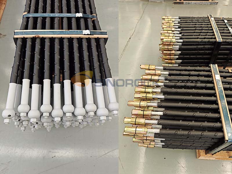
Pre-Assembled Design and Product Configuration

One of the practical features of the combination rock bolt is its pre-assembled configuration.

The main assembly consists of:

  • Hexagonal nut
  • Spherical grouting capsule
  • HDPE protective sleeve
  • Expansion shell anchorage assembly
  • Steel reinforcing bar

The bearing plate is supplied separately and can be installed by sliding it onto the bolt from the expansion-shell end until it reaches the designated grouting capsule position.

This configuration offers several practical advantages:

Simplified installation: Most major components are assembled before delivery, reducing the number of individual assembly operations required on site.

Reduced component handling: A preassembled configuration makes component management easier during transportation, storage, and construction.

Improved installation consistency: Factory assembly helps maintain the intended component arrangement and reduces the risk of incorrect on-site assembly.

Construction efficiency: Fewer individual installation operations can help streamline the construction process.

The final configuration can be adjusted according to the project design, bolt dimensions, grouting requirements, and corrosion protection specifications.

Technical Specifications and Material Selection
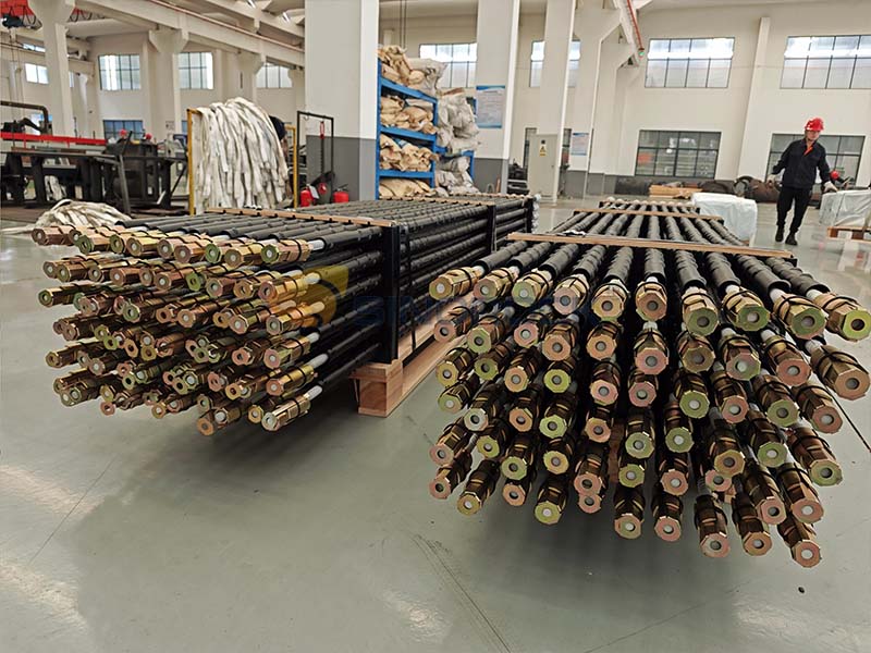
Technical Specifications and Material Selection

The combination rock bolt can be manufactured in different dimensions and material grades to meet various engineering requirements.

Item Technical Specification
Reinforcing bar material HRB400–HRB630
Bar diameter 16–32 mm
Thread specification M16–M33
Available threads M16, M18, M20, M22, M24, M27, M30, M33
Thread length Typically 150–200 mm
Maximum reference thread length ≤300 mm
Bar surface treatment Hot-dip galvanizing + epoxy coating

Reinforcing Bar Strength

The system uses HRB400–HRB630 reinforcing steel. The higher-strength grades provide greater tensile capacity and allow the system to accommodate different structural loading requirements.

The appropriate steel grade should be selected according to:

  • Required tensile capacity.
  • Bolt diameter and effective cross-sectional area.
  • Project design loads.
  • Ground conditions and deformation characteristics.
  • Applicable material and construction standards.

Thread Configuration

Both ends of the reinforcing bar are machined with threads. The threaded sections are used for component connections and load transfer within the assembly.

The reference thread specifications range from M16 to M33, covering different reinforcing bar diameters and engineering requirements.

Thread length is typically 150–200 mm, with configurations up to 300 mm available.

Thread dimensions should be coordinated with the nut, grouting capsule, and other connecting components to ensure proper engagement and assembly compatibility.

Key Considerations for Product Selection

When specifying a combination rock bolt, the following parameters should be confirmed:

  1. Required borehole diameter.
  2. Reinforcing bar diameter.
  3. Required tensile load or anchorage capacity.
  4. Steel bar length
  5. Steel grade.
  6. Thread specification and thread length.
  7. Corrosion protection requirements.
  8. Bearing plate dimensions.
  9. Expansion shell configuration.
  10. Grouting method and associated connections.

These parameters should be considered together rather than selected independently.

Multi-Layer Corrosion Protection System
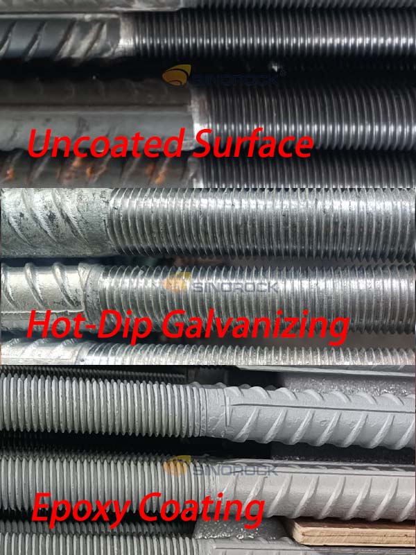
Multi-Layer Corrosion Protection System

In underground and geotechnical environments, steel reinforcement may be exposed to groundwater, moisture, chlorides, sulfates, and other aggressive substances.

Without adequate protection, corrosion can reduce the effective cross-sectional area of the steel and compromise its load-bearing performance.

To address these challenges, the combination rock bolt adopts a multi-layer corrosion protection system consisting of:

  1. Hot-dip galvanizing.
  2. Epoxy coating.
  3. HDPE protective sleeve.
  4. Cementitious grout sealing and encapsulation.

Each layer provides a different protective function.

Hot-Dip Galvanizing

Hot-dip galvanizing involves immersing steel components in molten zinc to form a metallurgically bonded zinc coating.

The zinc layer provides two main forms of protection:

Barrier protection: The coating separates the underlying steel from the external environment.

Sacrificial protection: Zinc is more electrochemically active than steel and can provide sacrificial protection when localized coating damage occurs under suitable conditions.

The reference standards include:

  • EN ISO 1461 – Hot-dip galvanized coatings on fabricated iron and steel articles.
  • GB/T 13912 – Hot-dip galvanized coatings on fabricated iron and steel articles.

Hot-dip galvanizing provides a fundamental corrosion protection layer for the reinforcing bar.

Epoxy Coating

Epoxy coating provides an additional protective barrier against moisture, chemicals, and other corrosive substances.

It works together with the galvanized layer to improve the overall durability of the steel components.

The reference standards include:

  • ISO 12944 – Corrosion protection of steel structures by protective paint systems.
  • GB/T 30790 – Paints and varnishes: Corrosion protection of steel structures by protective paint systems.

The required epoxy coating thickness should not be treated as a universal fixed value. It needs to be determined according to:

  • Environmental corrosivity category.
  • Expected service life.
  • Selected coating system.
  • Surface preparation requirements.
  • Coating adhesion and application quality.

HDPE Protective Sleeve

The HDPE protective sleeve provides a physical barrier around the designated steel sections.

Compared with relying exclusively on surface coatings, the sleeve introduces an additional protective element that helps limit direct contact between the steel and surrounding corrosive substances.

Cementitious Grout Protection

After injection and curing, cementitious grout encapsulates the designated anchoring sections and helps reduce the exposure of the steel reinforcement to external environmental agents.

The effectiveness of this protection depends on adequate grout filling, curing, and the absence of significant voids or defects.

This integrated approach makes the combination rock bolt suitable for projects where corrosion resistance and long-term durability are important design considerations.

Installation Procedure
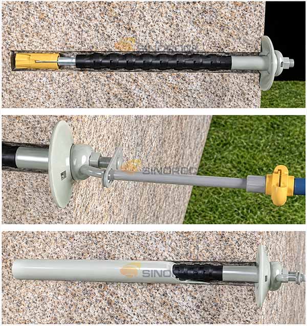
Installation Procedure

The combination rock bolt follows a mechanical anchoring and post-grouting installation process. The general construction sequence consists of five stages:

Step 1: Drilling

Drill a borehole into the rock mass according to the engineering design. The borehole diameter, depth, direction, and alignment must be compatible with the combination rock bolt.

Step 2: Bolt Insertion

Insert the preassembled combination rock bolt into the prepared borehole. Ensure that the expansion shell reaches its intended anchoring position and that the external components are correctly arranged.

Step 3: Mechanical Anchorage and Tensioning

Activate the expansion shell to establish mechanical contact with the borehole wall. Rotate the reinforcing bar or use the specified installation procedure to develop the required anchoring force and preload.

The installation process must ensure that the expansion shell is properly engaged before proceeding to grouting.

Step 4: Grouting

Connect the grouting equipment to the designated injection point. Inject cementitious grout through the grouting assembly according to the approved construction procedure. The grout should be distributed throughout the intended spaces around the bolt.

Injection pressure, grout consistency, volume, and completion criteria should be determined according to the project design and site conditions.

Step 5: Grout Curing and Final Anchorage

Allow the grout to cure under the specified conditions. After curing, the grout develops additional bonding and encapsulation around the anchoring system.

The completed bolt assembly provides combined mechanical and grouted reinforcement.

Key Installation Considerations

For reliable installation, several factors require particular attention:

  • Borehole diameter must match the expansion shell specifications.
  • The borehole must be sufficiently clean to allow proper installation.
  • The expansion shell must be correctly activated.
  • Preload should meet the engineering design requirements.
  • Grouting connections must be properly sealed.
  • Grout injection should be monitored to confirm adequate filling.
  • Corrosion protection components should not be damaged during handling or installation.

Proper installation is essential because the performance of the complete system depends not only on the material properties but also on the interaction between the mechanical anchorage, grout, and surrounding rock.

Engineering Applications
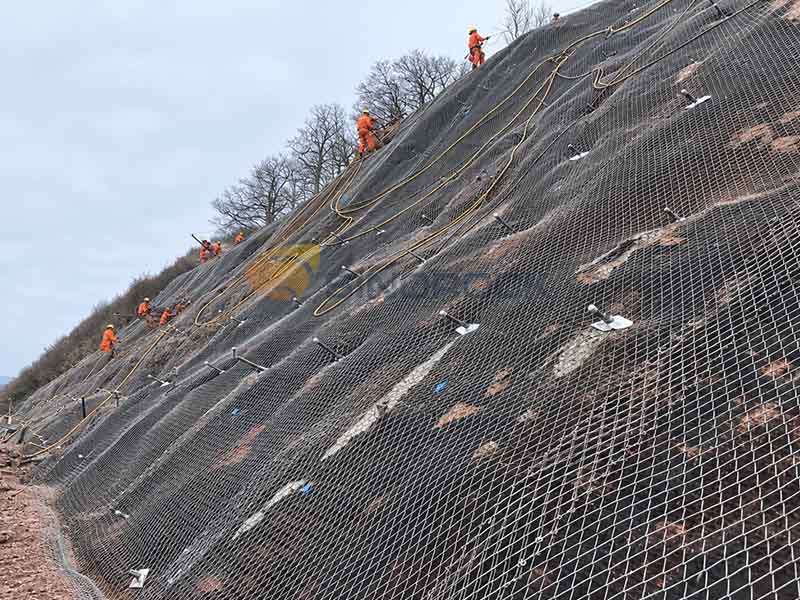
Engineering Applications

Combination rock bolts are designed for a wide range of geotechnical and underground engineering applications, particularly where mechanical anchorage, post-grouting, and enhanced corrosion protection are required.

Tunnel Engineering

In tunnel construction, surrounding rock may experience stress redistribution, deformation, water infiltration, and deterioration after excavation. Combination rock bolts can be used for initial support and subsequent reinforcement to improve the stability of the surrounding rock.

Typical applications include:

  • Road and railway tunnel reinforcement.
  • Underground tunnel support.
  • Secondary reinforcement of tunnel linings and surrounding rock.
  • Underground transportation infrastructure.
  • Subsea tunnel projects.

The mechanical anchorage mechanism provides initial support, while subsequent grouting contributes to long-term reinforcement and protection.

For tunnels exposed to groundwater or aggressive environmental conditions, the multi-layer corrosion protection system can be an important consideration in selecting the anchoring solution.

Mining and Underground Excavations

Mining operations frequently involve complex geological conditions, changing stress distributions, and potentially aggressive underground environments.

Combination rock bolts can be used for roof and sidewall reinforcement in underground mine roadways and excavations.

Typical applications include:

  • Coal mine roadway support.
  • Metal mine underground reinforcement.
  • Roof and sidewall stabilization.
  • Underground chambers and caverns.
  • Long-term reinforcement of underground openings.

The mechanical anchorage provides an initial support connection, while post-grouting contributes to the development of a more comprehensive anchoring system.

For deep mining operations, the bolt diameter, steel grade, anchorage capacity, and corrosion protection should be selected according to the actual ground stress and geological conditions.

Rock Slope Stabilization

Rock slopes may become unstable due to discontinuities, weathering, groundwater infiltration, and external loading. Combination rock bolts can be installed to reinforce unstable rock masses and improve their resistance to movement.

Typical applications include:

  • Highway and railway cut slopes.
  • Mountain road stabilization.
  • Rockfall prevention systems.
  • Infrastructure slope reinforcement.
  • Long-term stabilization of fractured rock masses.

The mechanical anchoring system provides an initial connection to the rock mass, while grouting helps improve the interaction between the bolt and surrounding ground.

Subsea Tunnels and Coastal Infrastructure

Subsea tunnels and coastal infrastructure projects often face particularly demanding corrosion conditions. The presence of saline groundwater, chloride ions, moisture, and other aggressive environmental agents can accelerate the corrosion of conventional steel reinforcement.

A combination rock bolt incorporates multiple protective layers, making it a potential reinforcement solution for:

  • Subsea tunnel reinforcement.
  • Coastal underground structures.
  • Marine infrastructure foundations.
  • Underground structures in saline environments.
  • Coastal transportation projects.

The combination of galvanizing, epoxy coating, HDPE protection, and cementitious encapsulation provides a comprehensive approach to corrosion protection.

Other Geotechnical and Underground Applications

Beyond tunnels, mining, and slope reinforcement, combination rock bolts may also be considered for:

  • Underground hydropower caverns.
  • Underground storage facilities.
  • Water conservancy projects.
  • Foundation reinforcement.
  • Underground chambers and infrastructure support.

The suitability of the system depends on the required anchorage mechanism, ground conditions, structural loading, and corrosion environment.

Combination Rock Bolt vs. Conventional Mechanical Rock Bolt
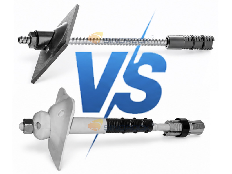
Combination Rock Bolt vs. Conventional Mechanical Rock Bolt

Although both systems use mechanical anchorage, their reinforcement mechanisms and long-term performance considerations are different.

Comparison Conventional Mechanical Rock Bolt Combination Rock Bolt
Primary anchorage Mechanical end anchorage Mechanical end anchorage + grouting
Initial support Yes Yes
Post-grouting Not normally included Integrated into the system
Load transfer Primarily through the mechanical anchorage Mechanical anchorage and additional grout bonding
Corrosion protection Depends on product configuration Multi-layer protection available
Long-term reinforcement Depends on anchorage and environmental protection Designed to combine mechanical and grouted reinforcement
Typical applications Hard-rock and temporary support Long-term underground and geotechnical reinforcement

The main difference is that a combination rock bolt incorporates a dedicated post-grouting system and additional corrosion protection components.

It therefore offers a more comprehensive reinforcement solution for projects where initial mechanical anchorage alone may not satisfy long-term support requirements.

Combination Rock Bolt vs. Self-Drilling Anchor Bolt
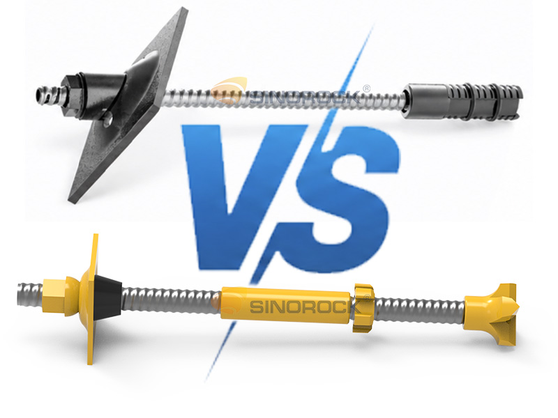
Combination Rock Bolt vs. Self-Drilling Anchor Bolt

Combination rock bolts and self-drilling anchor bolts both provide grouted reinforcement, but they are based on different construction principles.

Comparison Combination Rock Bolt Self-Drilling Anchor Bolt
Basic structure Solid reinforcing bar with mechanical anchorage assembly Hollow threaded steel bar
Drilling method Separate drilling followed by bolt insertion Drilling and installation integrated
Drill bit Separate drilling tool Sacrificial drill bit
Initial anchorage Expansion shell Primarily through grouting
Grouting sequence Post-grouting after mechanical anchorage Usually during or immediately after drilling
Main advantage Immediate mechanical anchorage and additional grouted reinforcement Efficient installation in difficult and fractured ground
Typical application considerations Projects requiring mechanical anchorage and long-term corrosion protection Projects requiring drilling, grouting, and anchoring in one integrated system

When Should You Choose a Combination Rock Bolt?

A combination rock bolt may be suitable when:

  • Immediate mechanical anchorage is required.
  • The project requires subsequent grouting.
  • Long-term corrosion protection is an important consideration.
  • The ground conditions allow the use of a conventional pre-drilled borehole.
  • The project requires a combination of mechanical and grouted reinforcement.

When Should You Choose a Self-Drilling Anchor Bolt?

A self-drilling anchor bolt may be more suitable when:

  • Ground conditions are loose, fractured, or unstable.
  • Borehole collapse makes separate drilling and bolt insertion difficult.
  • Construction space is restricted.
  • Drilling, grouting, and anchoring need to be integrated into one operation.
  • Conventional drilling methods are inefficient or unreliable.

The two systems serve different engineering requirements. Selection should be based on geological conditions, construction methods, structural loading, durability requirements, and overall project economics.

Quality Control and Performance Verification
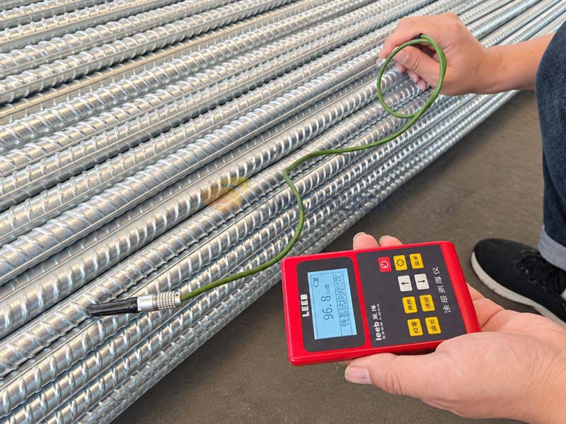
Quality Control and Performance Verification

The reliability of a combination rock bolt depends on the quality of its individual components and the performance of the assembled system. Quality control should cover the entire manufacturing and installation process.

Raw Material Inspection

The reinforcing bar should be inspected to verify:

  • Material grade.
  • Chemical composition.
  • Mechanical properties.
  • Diameter and dimensional tolerances.
  • Surface condition.

The material certificates and inspection records should be reviewed to confirm compliance with the specified requirements.

Thread and Component Inspection

The threaded sections should be checked for dimensional accuracy, thread integrity, and compatibility with the corresponding nuts and connecting components.

The expansion shell, grouting capsule, and bearing plate should also undergo dimensional and visual inspections.

Galvanizing and Epoxy Coating Inspection

The corrosion protection system requires particular attention. Relevant inspection items include:

  • Zinc coating thickness and uniformity.
  • Epoxy coating thickness.
  • Surface preparation.
  • Coating continuity.
  • Adhesion performance.
  • Damage caused during transportation and installation.

The inspection criteria should follow the specified coating standards and project requirements.

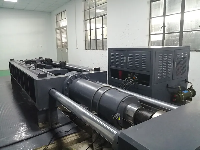
Mechanical Performance Testing

The mechanical performance of the complete anchoring assembly should be verified through appropriate testing.

Depending on the project requirements, testing may include:

  • Tensile strength testing.
  • Thread connection strength testing.
  • Expansion shell anchorage testing.
  • Pull-out testing.
  • Grouting performance verification.
  • Complete assembly load testing.

Testing the complete assembly is important because the overall anchoring capacity is influenced by the interaction of multiple components rather than the reinforcing bar alone.

CE Conformity Assessment
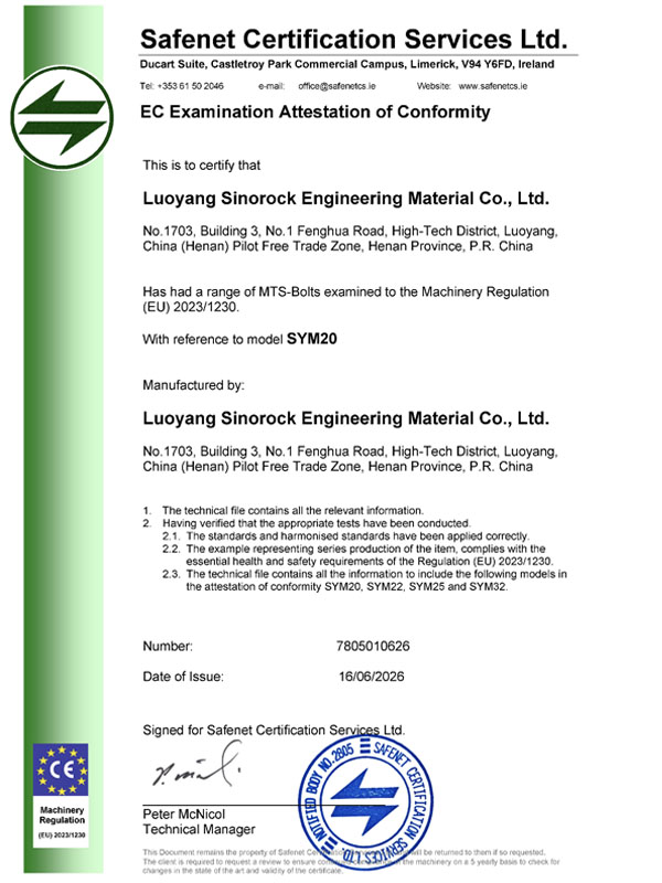
CE Conformity Assessment

Sinorock’s combination rock bolt product range has undergone conformity assessment in accordance with the Machinery Regulation (EU) 2023/1230. The examination was conducted by Safenet Certification Services Ltd., with reference to models SYM22, SYM25, and SYM32.

This provides customers with documented evidence of the product range’s conformity assessment and reflects Sinorock’s commitment to product quality, safety, and compliance with applicable European requirements.

Conclusion

The combination rock bolt is a versatile rock reinforcement system that integrates mechanical end anchorage, post-grouting, and multi-layer corrosion protection.

By combining immediate mechanical support with subsequent grouted reinforcement, it provides a practical solution for underground and geotechnical engineering projects requiring reliable anchorage and long-term durability.

Looking for a Combination Rock Bolt solution for your project? Contact Sinorock to discuss your technical requirements, product specifications, and customized anchoring solutions.

Rock bolts are widely used in tunnel construction to reinforce surrounding rock masses, control ground deformation, and improve excavation stability. In conventional tunnel support systems, rock bolts work together with shotcrete, wire mesh, and other support elements to form an integrated ground reinforcement system.

However, achieving reliable rock bolt performance depends not only on the mechanical properties of the steel bar but also on the quality of installation and grouting.

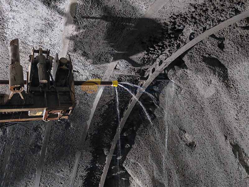
One particular challenge occurs when installing rock bolts in overhead or upward-inclined boreholes, especially along the tunnel crown. During grouting, air trapped inside the borehole may prevent the grout from completely filling the annular space between the bolt and the surrounding rock. Inadequate grout filling can leave internal voids and unprotected sections of the steel bar, potentially affecting bond performance and long-term durability.

A practical approach discussed in tunnel engineering research is the use of a separate vent pipe in hollow grouted rock bolt systems. By providing an additional passage for displaced air, this arrangement helps improve air evacuation during grouting and provides a more observable indication of grout filling.

This article examines the grouting challenges associated with tunnel crown rock bolts, explains the function of a separate vent pipe, and discusses the engineering considerations involved in improving grouting quality.

Why Is Grouting Quality Important in Tunnel Rock Bolt Installation?

Why Is Grouting Quality Important in Tunnel Rock Bolt Installation

In tunnel construction, rock bolts are commonly installed as part of the primary support system, particularly under the New Austrian Tunneling Method (NATM).

Their main function is to reinforce the surrounding rock mass and improve its overall stability. Depending on the geological conditions and support design, rock bolts may provide reinforcement through mechanisms such as:

  • Bonding between the bolt, grout, and surrounding rock.
  • Restraint of relative movement between rock blocks.
  • Improvement of the mechanical interaction within fractured rock masses.
  • Reduction of localized deformation around the excavation.
  • Integration with shotcrete and other support elements.

For fully grouted rock bolts, grout plays several important roles. It transfers load between the steel bar and the surrounding ground, helps protect the steel against corrosion, and contributes to the overall integrity of the anchoring system.

When grout does not completely fill the borehole, several potential problems may arise.

Incomplete Bonding

Air voids or unfilled sections can reduce the effective contact area between the grout and the borehole wall or bolt surface. This may affect load transfer and anchorage performance.

Reduced Corrosion Protection

Grout provides a protective environment around the steel bar. If sections remain exposed or inadequately covered, moisture and aggressive groundwater may increase the risk of corrosion.

Uncertain Installation Quality

A borehole may appear to have been successfully grouted even when internal voids remain. Without an appropriate venting and verification arrangement, it can be difficult to assess the actual filling condition.

These concerns become particularly important in tunnel crown applications, where gravity and borehole orientation can complicate the grouting process.

Common Grouting Challenges in Tunnel Crown Rock Bolts

Common Grouting Challenges in Tunnel Crown Rock Bolts

Air Entrapment in Upward-Inclined Boreholes

When grout is injected into a horizontal or downward-inclined borehole, air can generally move toward an available outlet more easily, depending on the injection arrangement.

The situation is more complicated in upward-inclined boreholes.

In tunnel crown applications, grout is typically injected through the hollow bar or another designated injection passage. As grout enters the borehole, the air initially occupying the annular space must escape.

If the air outlet is obstructed or becomes sealed prematurely by grout, trapped air may remain inside the borehole.

This can create internal voids even when grout appears at the borehole opening.

Premature Grout Return

One potential problem with conventional arrangements is premature grout return at the borehole entrance.

When grout reaches the outer end of the borehole before the trapped air has been completely displaced, the grout may block the available air escape path.

The resulting condition can create a false indication of complete grouting.

In other words, observing grout at the borehole opening does not necessarily confirm that the entire borehole has been filled.

Limitations of Conventional Grout Stoppers

A grout stopper is commonly installed near the borehole opening to prevent grout leakage.

However, a stopper must perform two different functions:

  • Restrict grout from flowing out of the borehole.
  • Allow displaced air to escape during injection.

If the stopper seals the borehole too tightly without a separate venting passage, air evacuation may become difficult.

If it does not provide adequate sealing, grout may leak through the gap between the stopper and the bolt or borehole wall.

This creates a practical challenge: achieving effective grout retention while maintaining a reliable air escape route.

Difficulties in Quality Verification

The actual grout filling condition is difficult to determine through visual inspection alone.

A visible grout return at the borehole entrance may indicate that grout has reached the outlet, but it does not automatically prove that no internal voids remain.

For this reason, the grouting arrangement, injection procedure, grout properties, and quality verification method should all be considered when designing tunnel rock bolt installation procedures.

A Separate Vent Pipe for Improved Grouting

A Separate Vent Pipe for Improved Grouting

A separate vent pipe provides an additional passage for air to escape during grouting.

This arrangement was investigated in a 2009 tunnel engineering study based on trial applications in the Dabie Mountain Tunnel in China.

The system used a hollow grouted rock bolt together with a dedicated vent pipe attached to the bolt body.

Rather than relying solely on the available clearance around the grout stopper, the separate pipe provided a defined route for air evacuation.

Main Components

A vented hollow grouted rock bolt arrangement generally includes the following components:

Hollow Bolt

The hollow steel bar serves as the structural anchoring element and provides an internal passage for grout injection.

Separate Vent Pipe

A small-diameter pipe is attached to the bolt body and extends toward the outside of the borehole. It provides a passage for displaced air during grouting.

Grout Stopper

The stopper is installed near the borehole entrance to limit grout leakage and help maintain the required injection conditions.

Grouting Connector

The connector connects the hollow bolt to the grouting equipment and provides access for grout injection.

Bearing Plate and Nut

These components are installed at the exposed end of the bolt to transfer support loads and secure the anchoring assembly according to the project design.

How the Venting Process Works

The basic working principle involves separate passages for grout injection and air evacuation.

  1. The hollow bolt is inserted into the prepared borehole with the vent pipe attached to its body.
  2. A grout stopper is installed near the borehole entrance.
  3. The grouting connector is connected to the exposed end of the hollow bolt.
  4. Cement-based grout is pumped through the hollow bolt into the borehole.
  5. As grout progressively fills the annular space, the displaced air escapes through the separate vent pipe.
  6. The vent pipe provides an observable outlet for monitoring air discharge and subsequent grout return.
  7. Grouting is stopped according to the approved project procedure and the observed return condition.

The key principle is to avoid allowing grout to seal the available air outlet before the trapped air has been displaced.

A separate venting passage can therefore help reduce the risk of air entrapment and improve the control of the grouting process.

Field Trial: Application in the Dabie Mountain Tunnel

Field Trial: Application in the Dabie Mountain Tunnel

The 2009 study, published in the Chinese journal Tunnel Construction, documented a field trial of the combined hollow grouted rock bolt arrangement in the Dabie Mountain Tunnel.

The trial focused on evaluating the construction procedure, air evacuation, grout filling, and installation efficiency.

The main test parameters reported in the paper included:

Parameter Trial specification
Bolt diameter 22 mm
Bolt length 2.5 m
Borehole diameter 40–42 mm
Borehole depth 2.5 m
Vent pipe diameter 8 mm
Vent pipe wall thickness 1 mm
Vent pipe length 3.6 m
Grout water-cement ratio Approximately 0.4–0.5
Grouting equipment High-pressure grouting pump

Grouting Procedure

The trial followed a sequence designed to maintain a separate air escape route throughout the injection process.

First, the borehole was drilled and cleaned using compressed air.

The vent pipe was then secured to the hollow bolt body, extending beyond the exposed end of the bolt. The bolt assembly was inserted into the borehole, and a grout stopper was installed to restrict grout leakage.

After connecting the grouting equipment, the vent pipe was kept open.

Grout was pumped through the hollow bolt. During injection, air escaped through the vent pipe. The trial reported that air discharge stopped after approximately 30 seconds, followed by the appearance of grout return after a further period of approximately 10 seconds.

These observations were used to assess the progress of borehole filling.

Transparent Tube Verification

In addition to the field installation, the research team conducted a simulated grouting test using a transparent acrylic tube.

The hollow bolt assembly was installed inside the tube, with both ends sealed. The grout was injected through the hollow bolt while the vent pipe was immersed in water so that air discharge could be observed.

During injection, bubbles were initially released through the vent pipe. After approximately 35 seconds, the bubbles stopped. Grout return was then observed through the vent pipe after a further period of approximately 10 seconds.

The researchers observed that the grout had filled the transparent tube, providing a visual demonstration of the venting arrangement.

This test helped illustrate the working principle of separate air evacuation during grouting.

It should be noted that the reported time values belong to the specific experimental arrangement and should not be treated as universal grouting parameters for other tunnel projects.

Key Advantages of a Separate Venting Arrangement

Key Advantages of a Separate Venting Arrangement

Based on the mechanism and the findings reported in the study, several potential advantages can be identified.

Improved Air Evacuation

A dedicated vent pipe provides a defined route for displaced air to leave the borehole during grout injection.

This is particularly relevant to upward-inclined and overhead rock bolt installations, where air entrapment can be more difficult to manage.

Better Control of Grout Filling

Separating the grout injection passage from the air evacuation passage helps reduce the possibility of premature blockage at the borehole entrance.

The observed air discharge and grout return also provide useful process information for site personnel.

More Observable Grouting Conditions

Compared with arrangements that rely only on grout appearance at the borehole opening, a separate vent pipe provides another observable indication of the grouting process.

However, this should be regarded as a process-monitoring method rather than definitive proof of complete grout filling.

Practical Construction Procedure

The study reported that the installation procedure was relatively straightforward and compatible with conventional hollow grouted rock bolt construction practices.

The additional operation mainly involved attaching the vent pipe to the bolt body.

According to the trial, each bolt required approximately 35–45 seconds for grouting. The additional preparation time for attaching the vent pipe was approximately 1–2 minutes per bolt.

These figures represent the conditions of the reported trial, rather than guaranteed production rates for other projects.

Important Engineering Considerations

Important Engineering Considerations

Although a separate vent pipe can help address air entrapment, successful grouting depends on more than the presence of a venting component.

Several factors should be considered during project planning and installation.

Borehole Orientation

The inclination and direction of the borehole affect how air moves as grout enters the annular space.

Tunnel crown applications should receive particular attention because upward-inclined holes may present greater air evacuation challenges.

Grout Consistency and Flowability

Grout properties influence injection pressure, flow behavior, and the ability of the material to fill the available space.

The water-cement ratio, cement type, admixtures, and mixing procedure should be selected according to project requirements.

A mixture that is too thick may create difficulties during injection, while excessive fluidity may increase leakage or segregation risks.

Vent Pipe Position and Continuity

The vent pipe must remain open and properly connected to the intended air escape route throughout the grouting process.

Blockages, disconnections, or incorrect positioning can affect its effectiveness.

Grouting Pressure and Equipment

The grouting pump should provide a suitable and controllable injection pressure.

Excessive pressure may cause grout leakage, damage components, or create undesirable effects in weak surrounding ground.

The appropriate pressure and injection procedure must be determined based on the ground conditions, bolt system, and project specifications.

Corrosion Protection

The grouted length and the exposed anchoring components should be considered separately when assessing corrosion protection.

Areas around the bearing plate, nut, and bolt head may require additional protective measures depending on the groundwater conditions, service life, and project durability requirements.

A separate vent pipe improves the air evacuation arrangement but does not independently provide corrosion protection.

Quality Inspection and Verification

Grout return from a vent pipe can provide an indication that grout has reached the vent outlet. Nevertheless, it should not be considered conclusive evidence that the entire borehole is free of voids.

For critical applications, project-specific inspection and verification methods may include:

  • Monitoring grout pressure and injection volume.
  • Recording grout return conditions.
  • Inspecting representative trial installations.
  • Conducting pull-out or proof-load tests where required by the design.
  • Applying suitable non-destructive or other verification methods when specified.

The acceptance criteria should follow the applicable project specifications and engineering standards.

Hollow Grouted Rock Bolts and Self-Drilling Anchor Bolts: Understanding the Difference

Hollow Grouted Rock Bolts and Self-Drilling Anchor Bolts

Hollow grouted rock bolts and self-drilling anchor bolts are both used in ground reinforcement, but they are not interchangeable terms.

Understanding their differences is important when selecting a suitable anchoring system for tunnel construction.

Hollow Grouted Rock Bolts

A conventional hollow grouted rock bolt is generally installed in a pre-drilled borehole.

The hollow bar serves as a grout injection passage, allowing grout to be delivered into the annular space around the bolt.

Depending on the system design, separate vent pipes and other accessories may be incorporated to improve the grouting process.

Self-Drilling Anchor Bolts

A Self-Drilling Anchor (SDA) system combines drilling and anchoring functions into one installation system.

Its hollow threaded bar acts as both the drill rod and the permanent reinforcement element. A sacrificial drill bit is attached to the front end, while grout is injected through the hollow bar during or after drilling, depending on the installation procedure.

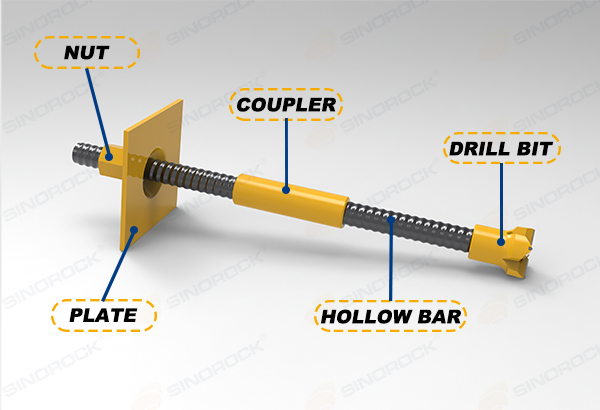
A typical SDA system includes:

  • Hollow threaded anchor bar.
  • Sacrificial drill bit.
  • Coupler.
  • Nut.
  • Bearing plate.
  • Centralizer.
  • Grouting accessories, where required.

Self-drilling anchor bolts are particularly useful in fractured rock, loose ground, and geological conditions where conventional boreholes may be difficult to maintain.

Selecting the Appropriate System

The selection between conventional hollow grouted rock bolts and self-drilling anchor bolts depends on geological conditions, borehole stability, installation access, support requirements, and construction methodology.

A separate vent pipe arrangement addresses a specific grouting challenge. It should not be confused with the drilling and anchoring functions of an SDA system.

Conclusion

Grouting quality is an essential factor in the performance and durability of tunnel rock bolt support systems.

In upward-inclined and overhead boreholes, trapped air can prevent complete grout filling and create uncertainty about the actual installation condition.

A separate vent pipe provides an additional passage for air evacuation during grouting and offers a more observable indication of the filling process.

The field trial documented in the 2009 study demonstrated the practical application of this arrangement in a tunnel construction environment. Its findings highlight the importance of considering air evacuation, grout flow, borehole orientation, and quality verification when designing and implementing grouted rock bolt systems.

For modern tunnel projects, the key consideration is not simply selecting a hollow bolt with an injection passage, but ensuring that the complete installation system is suitable for the ground conditions and provides a controlled, verifiable grouting process.

At Sinorock, we focus on the development and manufacturing of self-drilling anchor bolt systems and hollow bar anchoring solutions for ground reinforcement applications. Understanding the interaction between anchoring components, grouting procedures, and geological conditions is an important part of supporting reliable tunnel and underground construction projects.

Selecting the right drill bit diameter for different self-drilling anchor bar sizes is essential for efficient drilling, proper grouting, and reliable ground reinforcement. The optimal diameter varies depending on the anchor bar specification, drill bit type, and geological conditions. In this guide, Sinorock explains the recommended and acceptable drill bit diameter ranges for different anchor bar sizes, covering carbide drill bits, steel drill bits, and clay bits, to help engineers and contractors make informed decisions for their projects.

Why Is Drill Bit Diameter Important for Self-Drilling Anchor Bars?

Drill Bit Diameter Selection Guide

Self-drilling anchor bars integrate drilling, grouting, and reinforcement functions into a single system. They are widely used in slope stabilization, tunnel support, foundation reinforcement, and micropile applications.

Selecting the appropriate drill bit diameter is essential for achieving efficient drilling, suitable borehole dimensions, and sufficient space for grout flow. An undersized drill bit may result in insufficient annular clearance, while an oversized drill bit may increase drilling resistance, material consumption, and construction costs.

The ideal drill bit diameter depends on several factors, including anchor bar size, drill bit type, ground conditions, borehole requirements, and grouting methods.

Drill Bit Diameter Compatibility Guidelines

Drill Bit Diameter Compatibility Guidelines

Self-drilling anchor bars can be paired with different drill bit types according to the geological conditions and project requirements.

  • Carbide drill bits: Suitable for various rock formations, with selection depending on rock hardness, abrasiveness, and drilling requirements.
  • Steel drill bits: Used in suitable ground conditions, with compatible diameters selected according to the anchor bar specification and drilling requirements.
  • Clay bits: Designed for appropriate soft-ground conditions, where cutting performance, spoil removal, and borehole stability are important considerations.

For each anchor bar specification, the optimal drill bit diameter range should be the first reference for selection. The acceptable range provides additional options when project conditions require adjustments.

These ranges are intended as preliminary selection guidance. Final compatibility should be confirmed based on the ground conditions, drilling equipment, connection design, and project specifications.

Recommended Drill Bit Diameters for Different Anchor Bar Sizes

The following tables provide recommended and acceptable drill bit diameter ranges for different self-drilling anchor bar specifications. All dimensions are in millimeters (mm).

Carbide Drill Bit Diameter Compatibility

Carbide Drill Bit Diameter Compatibility

Bar Size Optimal matching drill bit outer diameter (mm) Acceptable drill bit outer diameter (mm)
R25 42~51 35~64
R28 42~51 38~76
R32 51~76 42~100
R38 64~90 56~120
R51 90~115 76~150
T30 51~76 42~100
T40 64~90 56~120
T52 90~115 76~150
T64 100~130 90~175
T73 130~175 100~200
T76 130~175 100~200
T103 200~250 170~300
T111 200~250 170~300
T127 220~300 200~350
T130 220~300 220~350
T150 300~400 250~450
T200 350~500 300~600

Steel Drill Bit Diameter Compatibility

Steel Drill Bit Diameter Compatibility

Bar Size Optimal matching drill bit outer diameter (mm) Acceptable drill bit outer diameter (mm)
R25 42~51 35~76
R28 42~51 38~90
R32 51~90 42~100
R38 64~100 56~130
R51 90~130 76~150
T30 51~90 42~100
T40 64~100 56~130
T52 90~130 76~150
T64 100~150 90~200
T73 130~175 100~220
T76 130~175 100~220
T103 200~250 170~350
T111 200~250 170~350
T127 220~300 200~380
T130 220~300 220~400
T150 300~400 250~450
T200 350~500 300~600

Clay Bit Diameter Compatibility

Clay Bit Diameter Compatibility

Bar Size Optimal matching drill bit outer diameter (mm) Acceptable drill bit outer diameter (mm)
R25 64~90 51~130
R28 64~90 51~130
R32 76~115 64~150
R38 90~115 64~150
R51 130~175 76~250
T30 76~115 64~150
T40 90~115 64~150
T52 115~175 76~250
T64 150~200 115~250
T73 175~250 150~300
T76 175~250 150~300
T103 250~300 200~350
T111 250~300 200~350
T127 275~320 220~380
T130 275~320 220~380

When selecting a drill bit, engineers should consider both the anchor bar specification and the drill bit type. The same anchor bar may require different drill bit diameters depending on the drilling method and ground conditions.

How to Select the Right Drill Bit Diameter

Select the Right Drill Bit Diameter

Identify the anchor bar specification

Determine the exact anchor bar model, such as R25. R32. R51. T76. or T103. Each specification has its own dimensional and compatibility requirements.

Evaluate the ground conditions

Consider rock hardness, abrasiveness, soil composition, fractured formations, and groundwater conditions to determine the most suitable drill bit type.

Refer to the optimal diameter range

Use the recommended range for the selected anchor bar and drill bit type as the primary selection reference. If the project requires a different borehole diameter, evaluate whether an alternative size is suitable.

Verify system compatibility

Check the connection between the drill bit and anchor bar, as well as drilling equipment capacity, spoil removal, grout clearance, and the specified borehole diameter.

For unusual geological conditions or non-standard configurations, consult the supplier before finalizing the selection.

What Happens If the Drill Bit Diameter Is Incorrect?

Drill Bit Diameter Is Incorrect

An unsuitable drill bit diameter may affect drilling performance and construction quality.

  • Diameter too small: May reduce annular clearance and restrict the space available for grout flow.
  • Diameter too large: May increase drilling resistance, bit wear, and material consumption, and may affect borehole stability under certain ground conditions.
  • Incorrect drill bit type: May reduce drilling efficiency or cause difficulties with spoil removal.
  • Incompatible connections: A suitable diameter alone does not guarantee compatibility between the drill bit and anchor bar.

The actual impact depends on geological conditions, drilling parameters, equipment configuration, and grouting methods.

Conclusion

Choosing the right drill bit diameter for a self-drilling anchor bar requires more than matching nominal sizes. The anchor bar specification, drill bit type, geological conditions, borehole requirements, and grouting process must all be considered.

Using the optimal diameter range as the primary reference can help engineers narrow down suitable options and improve drilling efficiency. Final selection should always be verified against project requirements and system compatibility.

Sinorock can assist with evaluating self-drilling anchor bar and drill bit combinations based on project specifications, ground conditions, and construction requirements.

An SDA bolt integrates drilling, reinforcement, and grouting into a single system. Instead of drilling a borehole first and installing a separate reinforcing element afterward, the hollow threaded anchor bar itself functions as the drill string during installation and remains in the ground as the permanent reinforcement element.

This integrated approach can simplify installation, reduce the number of separate operations, and provide greater adaptability to challenging ground conditions. However, understanding how an SDA system works requires more than simply knowing what the abbreviation stands for. The bar, drill bit, coupler, anchorage components, flushing method, grout, and surrounding ground all contribute to the performance of the completed system.

This guide explains what an SDA bolt is, how it works, its main components and types, common installation methods, and why simultaneous drilling and grouting can be important in difficult ground conditions.

What Does SDA Stand For?

What Does SDA Stand For

SDA stands for Self-Drilling Anchor.

An SDA bolt is generally based on a hollow threaded steel bar. A compatible sacrificial drill bit is attached to the leading end of the bar, allowing the bar to function as the drill string during installation.

The hollow center has two important functions:

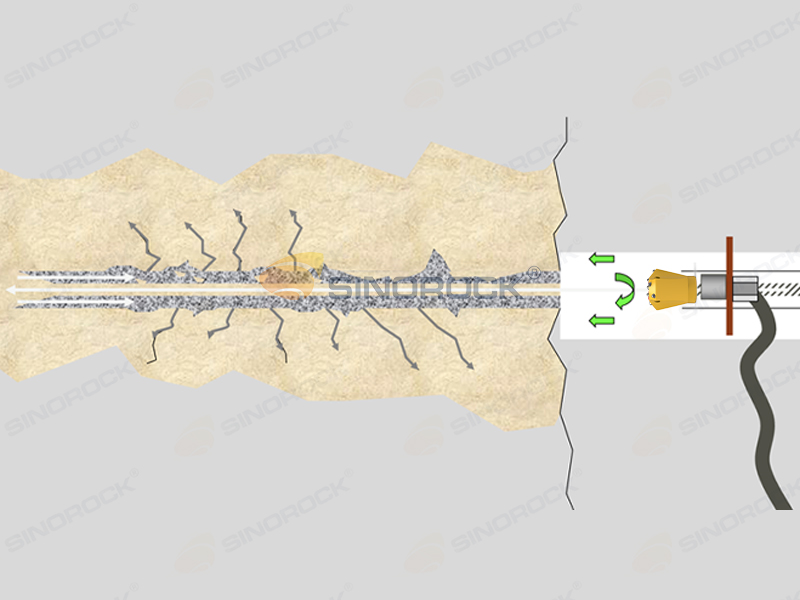
  • Flushing during drilling — air, water, foam, or grout can be introduced through the hollow bar depending on the installation method and ground conditions.
  • Grouting — cementitious grout can subsequently be injected through the bar to fill the annular space and form the bond between the steel reinforcement and surrounding ground.

Understanding what “SDA” stands for provides the basic definition, but it does not fully explain how the system differs from conventional anchors. To understand its engineering characteristics, it is useful to look more closely at what an SDA bolt actually is and how its hollow-bar design functions during installation.

What Is an SDA Bolt?

What Is an SDA Bolt

A Self-Drilling Anchor (SDA) Bolt is a hollow, continuously threaded steel anchor designed to perform drilling, reinforcement, and grouting as an integrated installation system. Unlike conventional anchoring methods, where a borehole may be drilled first and reinforcement installed afterward, an SDA bolt is installed together with a sacrificial drill bit and can remain in the ground as the permanent reinforcing element.

The hollow bar provides a passage for flushing media during drilling and for grout during installation. Once installed and grouted, the steel bar, grout, and surrounding ground work together to form a ground-reinforcement system.

The concept is particularly relevant where borehole stability, difficult ground conditions, restricted access, or the need to integrate drilling and grouting into fewer operations are important considerations.

An SDA bolt is therefore not simply a hollow steel bar with a drill bit. It is a complete anchoring system in which multiple components work together during drilling, grouting, and load transfer. Each component has a specific role in the installation and performance of the finished anchor.

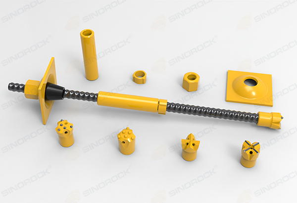
SDA Bolt Components

SDA Bolt Components

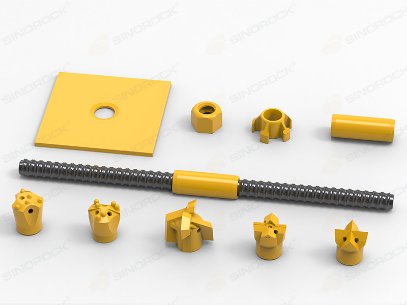
The performance of an SDA system depends on the compatibility of its individual components. Although the hollow anchor bar is the primary structural element, the drill bit, coupler, bearing plate, nut, and centraliser all contribute to installation efficiency, load transfer, and grout coverage.

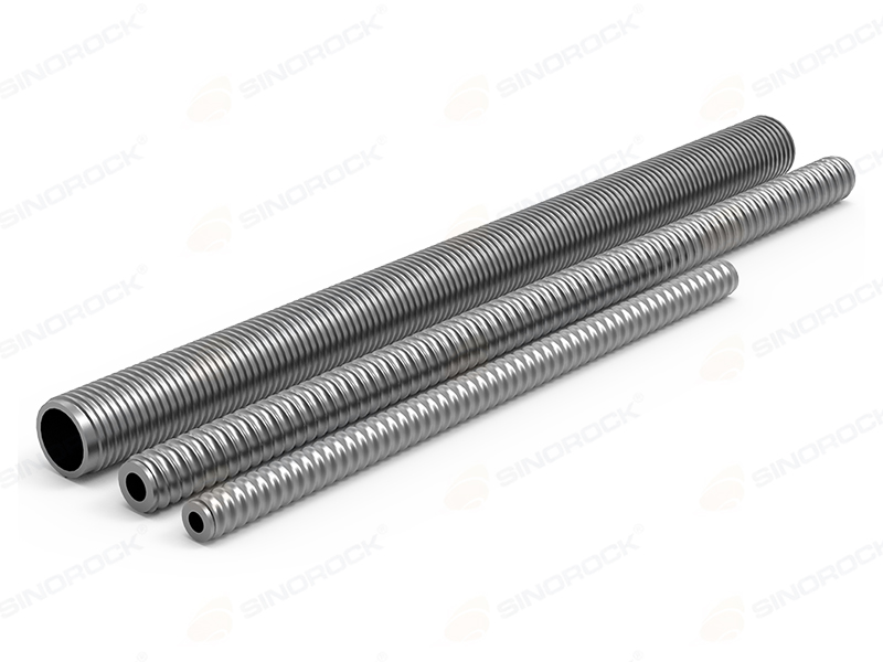
Hollow Anchor Bar

The hollow anchor bar is the primary structural component of an SDA system. It combines a continuous external thread, a hollow internal passage, a structural steel section, and connection capability

The continuous thread allows the bar to be cut or extended according to project requirements while maintaining compatibility with couplers and anchorage components.

While the hollow anchor bar provides the structural backbone of the system, it cannot perform the drilling operation by itself. A compatible drill bit is required to penetrate the ground and create the drilled hole.

Drill Bit

The drill bit is attached to the end of the SDA bar and performs the drilling operation.

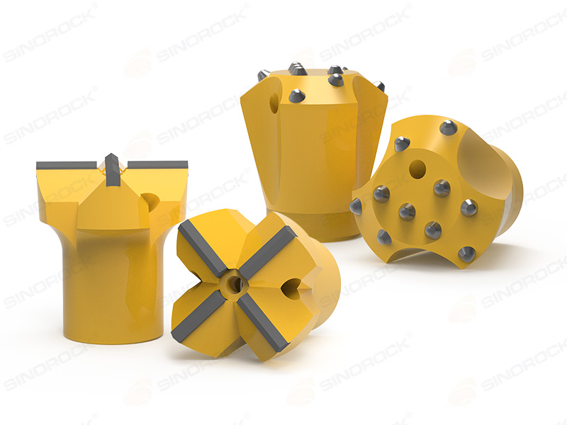
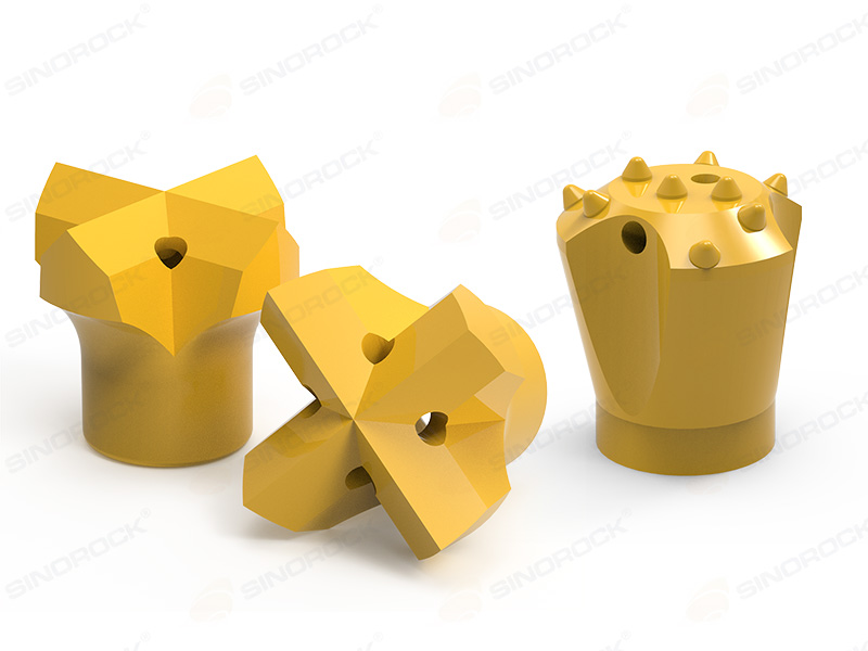
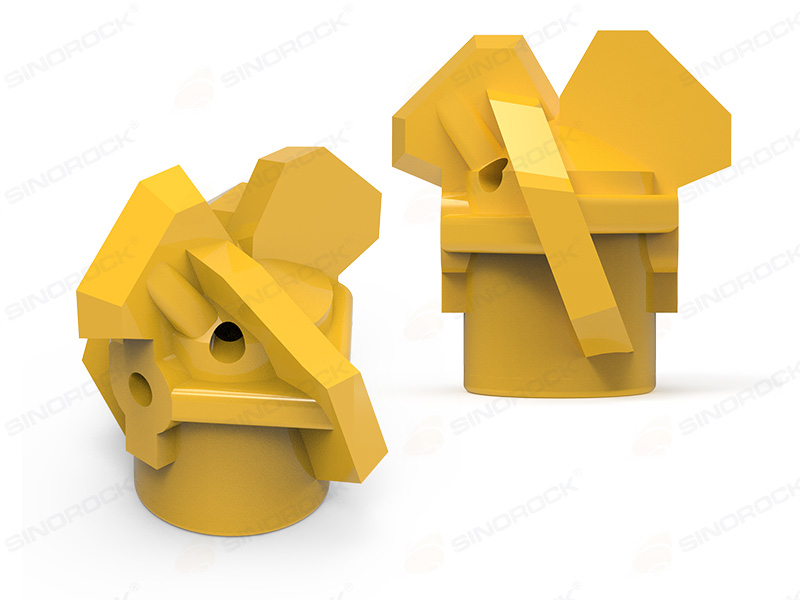
Different drill-bit configurations can be selected according to the geological formation. The available designs include various cross, three-blade, button, concave, and clay-bit configurations.

The drill bit is generally selected based on factors such as:

  • Soil or rock formation
  • Ground hardness
  • Presence of gravel
  • Fractured rock
  • Drilling method
  • Required borehole diameter
  • Flushing method

For many SDA applications, the drill bit is sacrificial and remains underground together with the anchor bar.

Because SDA bars can be installed to considerable depths, multiple bar sections may be required during drilling. Extension couplers provide the mechanical connection needed to continue the drilling operation without replacing the installed bar with a separate reinforcement element.

Extension Coupler

Extension couplers connect individual SDA bars together. They allow the system to achieve the required anchor or pile length without requiring a single bar manufactured to the full installation depth.

The coupler must be compatible with the corresponding SDA thread and designed to maintain the required mechanical connection.

Once the required anchor length has been achieved and the bar has been grouted, the load must be transferred from the steel reinforcement to the surrounding structure or facing. This is the role of the anchorage components.

Bearing Plate and Nut

The bearing plate distributes the load from the anchor head to the surrounding structure or facing system.

The nut secures the SDA bar against the bearing plate and completes the anchorage assembly.

These components are particularly important in soil and rock nailing, slope stabilization, and other applications where the anchor head must transfer forces to a facing or structural element.

In addition to the anchorage components, maintaining an appropriate position of the bar within the drilled hole can influence grout coverage and the resulting steel-to-grout interface. A centraliser can therefore be used where required by the system or installation design.

Centraliser

A centraliser helps maintain the position of the SDA bar within the drilled hole and supports more consistent grout coverage around the bar.

With the main SDA components identified, the next consideration is the selection of the anchor bar itself. SDA systems are available in different diameters, thread configurations, and steel grades, allowing the system to be selected according to the required mechanical and installation performance.

SDA Anchor Bar Types and Mechanical Properties

SDA Anchor Bar Types

SDA bars are not manufactured as a single universal configuration. Different bar sizes, thread profiles, and steel grades are available to accommodate different structural loads, drilling conditions, and project requirements. Among the commonly used configurations are R-type and T-type SDA bars.

R-Type SDA Bars

Typical R-thread SDA sizes shown for ground-engineering applications include:

SDA Type Ultimate Load Yield Load
R32L 210 kN 160 kN
R32N 280 kN 230 kN
R32S 360 kN 280 kN
R38N 500 kN 400 kN
R51L 550 kN 450 kN
R51N 800 kN 630 kN

R-type bars represent one commonly used configuration, while T-type systems provide another thread geometry and mechanical configuration. The appropriate selection depends on the requirements of the specific application rather than on thread type alone.

T-Type SDA Bars

The same technical range also includes T-thread systems, such as T30. T40 and T52 configurations, with different load capacities.

SDA Type Ultimate Load Yield Load
T30/16 220 kN 180 kN
T30/14 260 kN 220 kN
T30/11 320 kN 260 kN
T40/20 540 kN 430 kN
T40/16 660 kN 525 kN
T52/26 929 kN 730 kN

Mechanical properties define the capacity of the steel component, but the performance of an SDA system depends on more than the bar itself. Installation conditions, drilling parameters, grout quality, bond with the surrounding ground, and the final load-transfer mechanism all influence the behavior of the completed system.

To understand this interaction, it is useful to look at how an SDA bolt is installed and how the individual components work together from drilling through to anchorage.

How Does an SDA Bolt Work?

How Does an SDA Bolt Work

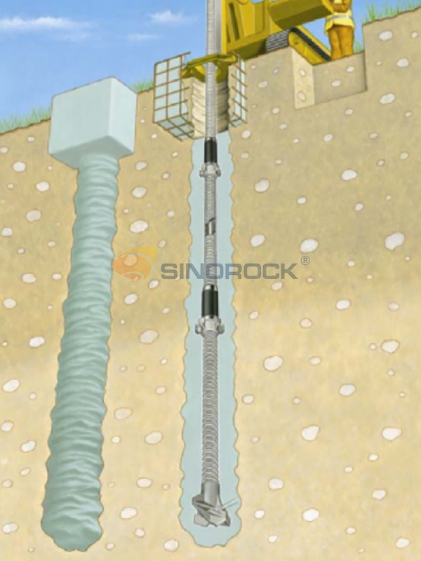
The fundamental principle of an SDA bolt is that the same hollow steel bar performs two functions during installation: it acts as the drill string during drilling and becomes the permanent reinforcement after installation.

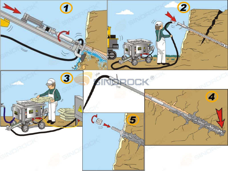
A typical installation sequence consists of:

Drilling

The SDA bar is connected to a suitable drill bit and advanced into the ground using rotary-percussion or rotary drilling.

Flushing

Air, water, foam, or grout can be introduced through the hollow center of the bar to remove drilling debris and maintain the borehole during installation.

Extension

When the required drilling depth exceeds the length of one bar, additional SDA bars can be connected using threaded couplers.

Grouting

Grout is introduced through the hollow bar. Depending on the ground conditions and installation method, drilling and grouting can also be carried out simultaneously.

Anchorage

After drilling and grouting are completed, the exposed end of the SDA bar is fitted with the required bearing plate and nut.

The resulting load-transfer mechanism can be represented as: Hollow Bar → Grout → Surrounding Ground

This simplified sequence illustrates the basic load-transfer path of an SDA system. The hollow bar carries the structural load, grout transfers the load from the steel to the surrounding ground, and the ground provides the ultimate resistance through the bonded zone.

SDA Installation Methods

SDA Installation Methods

The installation sequence explains the basic operation of an SDA bolt, but the actual drilling and grouting process can vary considerably depending on the ground conditions. Selecting an appropriate flushing and installation method is therefore an important part of SDA system performance.

Water Flushing

Water flushing is identified for dense sand, gravel formations, and rock conditions. Its functions include transporting larger drilling cuttings away from the borehole, cooling the drill bit, and supporting the drilling process

However, water should not automatically be selected for every ground condition. EN 14490 notes that, for self-drilled hollow-bar soil nails in unstable ground, the stabilizing fluid must be suitable for the ground, and that water should not be used where it increases instability or reduces bond capacity.

The choice of flushing medium should therefore be based on the actual ground conditions rather than treated as a standard selection for all SDA installations. Where water may adversely affect borehole stability or the grout-ground interface, alternative flushing methods may be more appropriate.

Air or Foam Flushing

Air and foam flushing can be used in softer ground conditions such as soft chalk and clay, particularly where excessive water discharge needs to be avoided.

In ground that is loose, unstable, or particularly sensitive to borehole collapse, flushing alone may not provide sufficient support to the drilled zone. In such situations, drilling and grouting can be combined to provide additional stabilization during installation.

Simultaneous Drilling and Grouting

In unstable formations, maintaining an open borehole can be one of the principal construction challenges. Loose sands, gravels, fractured formations, and weak ground may be susceptible to borehole collapse or loss of drilling fluid.

Among the available SDA installation methods, simultaneous drilling and grouting is particularly important when the stability of the drilled hole is a major construction concern. With simultaneous drilling and grouting, grout can be introduced during drilling, helping to stabilize the drilled zone and fill the space surrounding the installed anchor.

This method can:

  • Help stabilize the borehole during installation
  • Improve grout coverage along the anchor
  • Allow grout to penetrate surrounding ground
  • Improve the potential ground-to-anchor interface
  • Combine drilling and grouting into a single operation

EN 14490 likewise recognizes self-drilled hollow-bar soil nails and notes that simultaneous drilling and grouting can produce an enlarged grout body under some ground conditions. It also emphasizes that drilling rate, grout pressure, and flow rate should be adjusted to the ground conditions and design requirements.

Conclusion

A Self-Drilling Anchor (SDA) bolt is more than a hollow threaded steel bar with a drill bit. It is an integrated ground-engineering system that combines drilling, flushing, grouting, reinforcement, and load transfer within an installation process.

One of the key advantages of SDA technology is its adaptability to challenging ground conditions, particularly where conventional drilling and subsequent installation of reinforcement may be difficult. By allowing drilling and reinforcement to be integrated into a single system, SDA technology can provide a practical solution for soil nailing, slope stabilization, micropiles, tunneling, foundations, and other ground-engineering applications.

Sinorock FAQs

FAQs of Sinorock background

Find answers about Sinorock products, applications, and technical solutions.
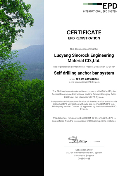
Request a Quote from SINOROCK

Submit your requirements and our team will get back to you within 24 hours.
Contact Form
Your information is safe with us and will not be shared.
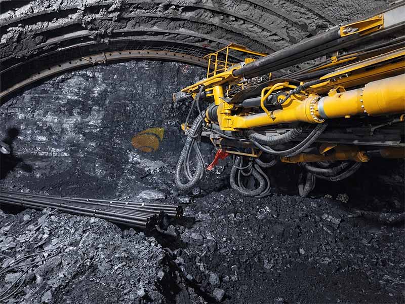
Scroll to Top

Get A Quote Now !

Contact Form
Your information is safe with us and will not be shared.
Need a quote or more information? We're here to help!
popup team